PCB Flex Circuits
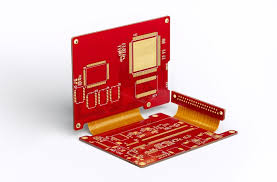
PCB flex circuits are an essential part of many electrical and mechanical products. They allow for a much smaller, lighter-weight design while still providing all of the functionality of traditional rigid boards. This is achieved by incorporating a very thin copper-clad film that is sandwiched between flexible and rigid sections of the circuit board.
As a result of this unique construction, there are a few key points to consider when designing PCB flex. This includes focusing on the materials used, as they can greatly impact how the circuit performs in real-world applications. Additionally, it is vital to understand how the fabrication process for pcb flex affects performance and durability.
The first step in creating a pcb flex is to decide the material to use as the base substrate layer. There are a few common choices, including polyimide (PI), PET and glass fiber epoxy. The PI option is the most popular choice, as it offers exceptional resistance to chemical damage and is also heat resistant. It is available in a variety of thicknesses, from as thin as 1/3 mil to 3 mils.
How Are PCB Flex Circuits Manufactured?
After the base layer is selected, copper cladding is applied using either a sputter deposition process or a chemical-immersion plating method. This step is followed by etching and drilling of the layers, as well as forming vias and openings. Finally, durable PI coverlay is laminated to the entire structure, protecting it from moisture and other contaminants.
If the flex section is not combined with a rigid section, it may be necessary to add a stiffener to help support the conductors. This provides a solid structure that will resist bending and vibration, as well as provide a route for signals to travel between the rigid and flex sections of the circuit board.
To make the traces on a flex circuit more flexible, it is often a good idea to change their width. This will reduce the amount of resistance they generate when bending and moving, as well as allow for wider end caps to protect the copper from physical damage.
When preparing the etch mask for a flex circuit, it is important to choose one that will provide a good balance between flexibility and durability. A good option is a chemical-resistant, abrasion-resistant and halogen-free etch mask. This will be able to withstand repeated etching cycles while providing excellent resistance to corrosion and high temperatures.
Once the etch mask is created, it is applied to the flex section of the circuit using an adhesive. This is followed by a hard-coating, which provides additional protection and increases the lifespan of the flex circuit. In addition, a UV-curable coating can be added to the flex circuit for increased resistance to humidity and ultraviolet radiation. Lastly, the conductive metal is etched and plated using a standard solder mask. The resulting PCB is then cut from the flex using either a hydraulic punch and die set for high-volume production, or a blanking knife for prototypes and low-volume manufacturing.